The Complete Resistor Guide: How to Read Values, Pick the Right Rating, and Actually Do the Circuit Math
If you have ever popped the back off anything with a circuit board inside, you have seen resistors. They are the little striped cylinders, the tiny black rectangles, the ceramic blocks bolted to a heatsink. They are everywhere, and most of them look like they should be interchangeable — yet a 220 Ω part and a 10 kΩ part are about as similar as a paperclip and a coat hanger.
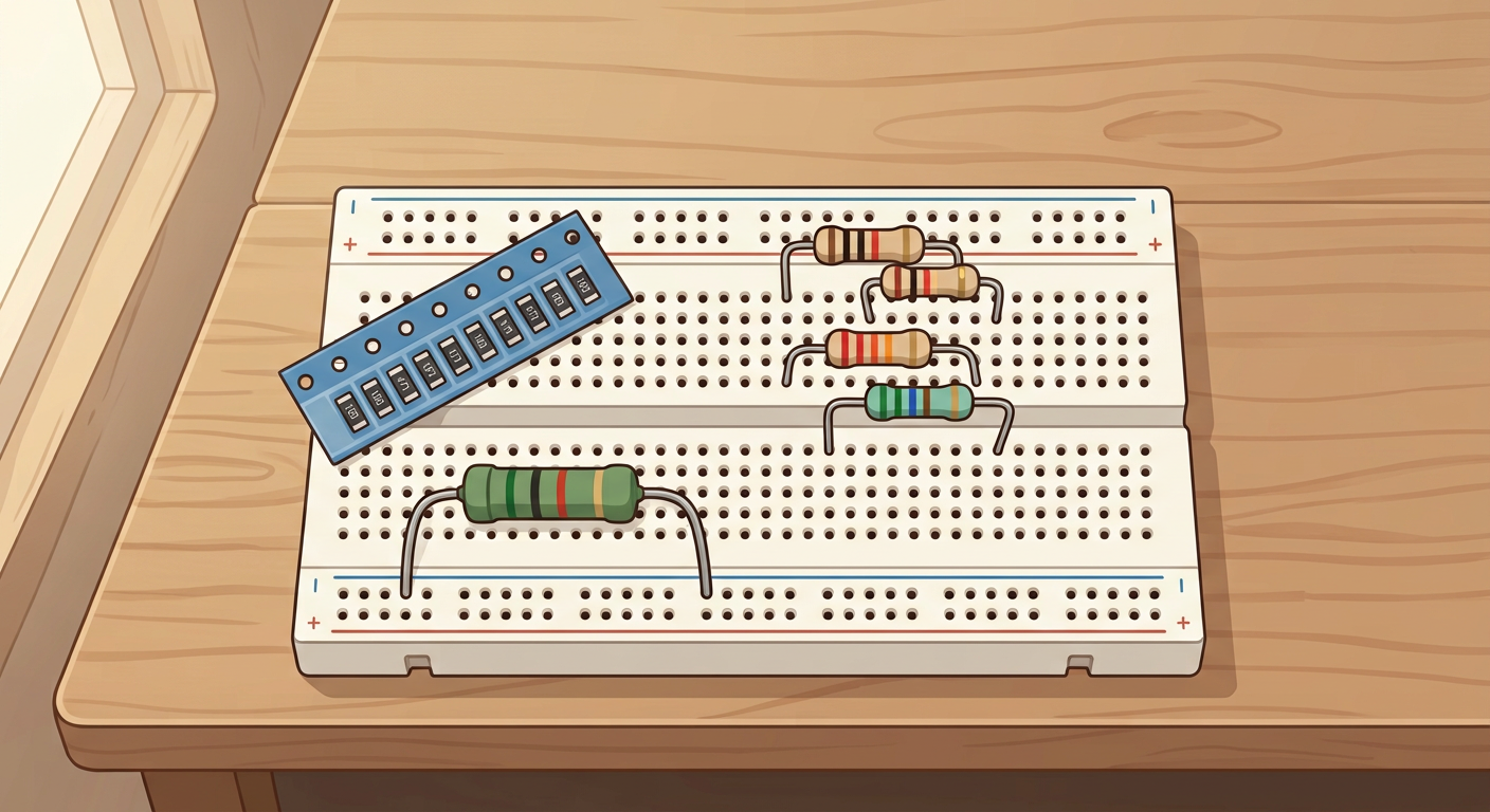
This guide is the page I wish every beginner landed on first. By the end you will be able to read any resistor by eye, know why a 47 Ω value exists instead of a sensible 50 Ω, pick a part that will not catch fire, and work through the three bits of math that cover maybe 90% of real-world resistor use. Where it helps, we have dropped in interactive tools — a 3D component you can spin, a color-code decoder, and live simulator circuits — because resistors are physical things, and seeing one move beats reading about it.
If you already know the rough answer and just need a specific value, jump to our pages on the [220 Ω resistor](/components/resistor/220-ohm-resistor), the [1 kΩ resistor](/components/resistor/1k-ohm-resistor), or the [10 kΩ resistor](/components/resistor/10k-ohm-resistor). Everything else lives in the [resistor category](/components/resistor).
What a resistor actually is (and why your circuit cannot live without one)
A resistor is a two-legged component whose only job is to get in the way. It opposes the flow of electric current, and it does so by turning some of that electrical energy into heat. That is the whole trick. No moving parts, no magic, just a controlled amount of "don't."
The amount of opposition is called resistance, measured in ohms (symbol: Ω, the Greek capital omega). One ohm is the resistance you get when one volt of pressure pushes one amp of current through. That definition is worth holding onto, because it tells you exactly what a resistor is doing in plain terms: it sets the relationship between voltage (pressure) and current (flow).
The rule that ties those three together is Ohm's law:
V = I × R
Voltage equals current times resistance. Rearrange it however you like — I = V / R or R = V / I — and you have the single equation that explains every resistor in every circuit.
Here is the mental model that actually sticks. Think of current as water flowing through a hose. Voltage is the water pressure from the tap. A resistor is a constriction in the hose — a kink, a narrow section, a thumb pressed over the end. The tighter the constriction, the less water gets through for a given pressure. A 10 kΩ resistor is a tight kink; a 10 Ω resistor is barely there.
Two things follow from this, and they explain most resistor behavior:
1. A resistor cannot create energy, only waste it. Engineers call it a *passive* component. It does not amplify, it does not oscillate, it just sits there converting current into a little warmth. (That "little warmth" is exactly why a too-small resistor smells bad and lets out smoke — more on that later.)
2. The resistance comes from the material, not the label. At the microscopic level, a resistor is made from a conductor that is deliberately not a great conductor — carbon, a metal-oxide film, a coiled wire. Electrons trying to cross it keep bumping into atoms, and each bump is a tiny conversion of motion into heat. Change the material, its length, its thickness, or its temperature, and you change the resistance.
That is the whole conceptual foundation. Everything below is just applying it.
Reading resistor values: color codes, demystified
Through-hole resistors (the striped cylinders) almost never have numbers printed on them — there is no room, and the paint would wear off. Instead they carry their value as colored bands. Once you learn the code, you can read a resistor across a room.
Most resistors you meet are 4-band, 5-band, or 6-band:
- 4-band (the common hobbyist part): two digits — a multiplier — a tolerance band. - 5-band (precision parts): three digits — a multiplier — a tolerance band. - 6-band: same as 5-band, plus a final band for temperature coefficient.
The first one to three bands are the *significant digits*. The next band is the *multiplier* — it tells you how many zeros to tack on (or, for gold and silver, a fraction). The band after that is *tolerance* — how far off the real value is allowed to be.
Here is the full table:
| Color | Band name | Digit | Multiplier | Tolerance | Tempco (ppm/°C) |
|---|---|---|---|---|---|
| Black | 0 | ×1 | 250 | ||
| Brown | 1 | ×10 | ±1% | 100 | |
| Red | 2 | ×100 | ±2% | 50 | |
| Orange | 3 | ×1 k | 15 | ||
| Yellow | 4 | ×10 k | 25 | ||
| Green | 5 | ×100 k | ±0.5% | 20 | |
| Blue | 6 | ×1 M | ±0.25% | 10 | |
| Violet | 7 | ×10 M | ±0.1% | 5 | |
| Grey | 8 | ×100 M | ±0.05% | 1 | |
| White | 9 | ×1 G | |||
| Gold | ×0.1 | ±5% | |||
| Silver | ×0.01 | ±10% | |||
| None | ±20% |
Three worked examples you will see constantly
A 220 Ω resistor (the classic LED current-limiter): Red — Red — Brown — Gold → 2, 2, ×10, ±5% = 22 × 10 = 220 Ω ±5%. This is the part we reach for on a 5 V logic rail or a bright LED. Full details on the [220 Ω resistor page](/components/resistor/220-ohm-resistor).
A 1 kΩ resistor (the default pull-up / current-limiter): Brown — Black — Red — Gold → 1, 0, ×100, ±5% = 10 × 100 = 1,000 Ω = 1 kΩ ±5%. If a tutorial says "just use 1k," this is the stripe pattern. See the [1 kΩ resistor page](/components/resistor/1k-ohm-resistor).
A 10 kΩ resistor (the standard microcontroller pull-up): Brown — Black — Orange — Gold → 1, 0, ×1,000, ±5% = 10 × 1,000 = 10,000 Ω = 10 kΩ ±5%. Almost every Arduino "connect a button" sketch assumes a 10 kΩ pull-up. More on the [10 kΩ resistor page](/components/resistor/10k-ohm-resistor).
### A mnemonic that actually works
The digits map to a sentence everyone learns: "Bad Beer Rots Our Young Guts But Vodka Goes Well — Get Some Now." Black, Brown, Red, Orange, Yellow, Green, Blue, Violet, Grey, White, (Gold, Silver, None). Silly, but you will never forget the order.
Interactive Resistor Color Code Calculator
Surface-mount resistors and their secret codes
Once you leave the breadboard and move to a manufactured board, resistors shrink into tiny black rectangles with no room for stripes. They carry numbers instead, and the system is simpler than it looks.
3-digit code (5% and 10% parts): the first two digits are significant, the third is the number of zeros.
- `471` = 47 followed by one zero = 470 Ω - `103` = 10 followed by three zeros = 10 kΩ - `100` = 10 followed by zero zeros = 10 Ω
4-digit code (1% parts): three significant digits, then the number of zeros.
- `4700` = 470 followed by no zeros = 470 Ω - `1002` = 100 followed by two zeros = 10 kΩ
EIA-96 code (1% precision on tiny packages): two digits plus a letter. The digits are an index into the E96 value table (01 = 100, 02 = 102 ... 96 = 976), and the letter is the multiplier: A = ×1, B = ×10, C = ×100, D = ×1 k, E = ×10 k, F = ×100 k (and a few others for sub-ohm values). So `01A` = 100 × 1 = 100 Ω, and `68A` = 487 × 1 = 4.87 kΩ.
You will also see a package size like 0402, 0603, 0805, or 1206. Those four digits are the size in hundredths of an inch: 0402 is 0.04 × 0.02 inches. Smaller is cheaper and lighter but harder to solder by hand and carries less power. A 1206 can usually take about 0.25 W; a 0402 is often rated at just 1/16 W (0.0625 W), which is why power math matters so much on tiny boards.
Rule of thumb: build on a breadboard or by hand, use through-hole; design a PCB you will manufacture, use SMD — and size the package to the wattage, not just the value.
Why resistors come in weird values: the E12 and E24 series
Here is a question that trips everyone up. Why is there a 47 Ω resistor and a 4.7 kΩ resistor, but no 50 Ω or 5 kΩ in the common bins? Why 33 Ω and 330 Ω instead of a round 30?
The answer is that resistor values are spaced geometrically, not arithmetically. Manufacturers do not pick random numbers; they use the E-series. An E12 resistor (±10% tolerance) has 12 values per decade, and each one is about 21% larger than the last — because a part can drift by up to 10% either way, the next value needs to start roughly where the previous one could have ended. The E12 values are:
10, 12, 15, 18, 22, 27, 33, 39, 47, 56, 68, 82 — then ×10 for the next decade (100, 120, 150 ...).
E24 (±5% tolerance) squeezes in 24 values per decade by halving that step:
10, 11, 12, 13, 15, 16, 18, 20, 22, 24, 27, 30, 33, 36, 39, 43, 47, 51, 56, 62, 68, 75, 82, 91.
That is why 47 Ω exists: it is the E12/E24 value nearest a "round" 50, and the geometric spacing guarantees that no matter which value you need, a standard part is close enough that tolerance absorbs the rest. Finer series — E48, E96, and E192 — exist for precision work (1%, 0.5%, and tighter), which is exactly where you saw the EIA-96 marking above come from.
The practical takeaway: when a design calls for "about 5 kΩ," you reach for the standard 4.7 kΩ or 5.1 kΩ, not a custom 5.00 kΩ part. Standard values are cheaper, always in stock, and what every calculator and simulator assumes.
Power ratings and tolerance: the specs that actually burn
This is the section most thin guides skip — and the one that determines whether your circuit works next week or smells like burnt plastic tomorrow.
### Wattage
Every resistor has a power rating in watts (W). The common through-hole sizes are 1/4 W (0.25 W), 1/2 W (0.5 W), 1 W, and up into the many-watt "power resistor" range. The rating is the maximum heat the part can shed into still air without overheating.
Three formulas tell you how much power a resistor is actually dissipating. They are all the same idea, just solved for what you happen to know:
> P = I² × R · P = V² / R · P = V × I
Worked example. Put a 220 Ω resistor straight across a 5 V supply. Using P = V² / R: 25 / 220 ≈ 0.114 W. That is 114 mW, comfortably under a 1/4 W part's 250 mW limit. Safe.
Now try a 10 Ω resistor across the same 5 V rail: 25 / 10 = 2.5 W. A 1/4 W resistor would be dissipating ten times its rating — it would glow, then fail. You would need a proper power resistor here. The value was "fine" by Ohm's law; the wattage is what bit you.
### Tolerance: when 5% is plenty and when it is not
Tolerance is how far the real resistance can drift from the labeled value. A ±5% 1 kΩ resistor is anywhere from 950 Ω to 1,050 Ω. A ±1% part stays between 990 Ω and 1,010 Ω.
For most jobs — limiting an LED, pulling up a pin, setting a gain roughly — 5% is perfectly fine and cheaper. Reach for 1% (or better) when the resistor sets a precision reference: a measurement divider, a filter frequency, an ADC scaling network. There, a 5% shift changes the answer you read.
### Temperature coefficient (tempco)
The sixth band on a precision resistor is its temperature coefficient of resistance (TCR), given in ppm/°C — parts per million per degree Celsius. A 100 ppm/°C resistor changes by 100 Ω per million ohms (0.01%) for every 1 °C of temperature shift. Brown's 100 ppm is typical for cheap film; grey's 1 ppm is laboratory-grade. For anything indoors at room temperature, tempco barely matters; for a sensor you leave in the sun or a meter you trust, it is the difference between "close" and "wrong."
### The derating curve (this is the part that saves parts)
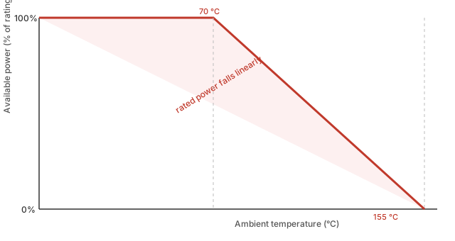
A resistor's wattage rating is only valid at a specific ambient temperature — usually 70 °C. Above that, it cannot shed heat as well, so the safe power drops. The standard curve (per IEC 60115-1, and you will see the same shape on every major datasheet) runs at 100% up to 70 °C, then falls in a straight line to zero watts at 155 °C.
What this means in practice: a resistor rated 1/4 W at room temperature is only good for about half that inside a sealed enclosure that sits at 110 °C. If your circuit runs hot, either pick a bigger package or do the math at the derated value, not the headline number.
Types of resistors and when to reach for each
Not all resistors are the same inside, and the differences show up as noise, precision, and how they behave at temperature and frequency.
Carbon film vs. metal film. For blinking an LED or pulling a pin high, carbon film is all you need and costs a fraction of a cent. Choose metal film when the resistor is in the signal path you actually care about — a preamp, a voltage reference, an ADC front-end — because its lower noise and tighter tempco keep the signal clean.
Wirewound and high-power. When wattage is the problem, wirewound parts (often ceramic-bodied, sometimes bolted down) are the answer. The catch: that coil of wire acts like a tiny inductor, so avoid them in high-frequency RF paths where a "resistor" that also stores magnetic energy misbehaves.
Variable resistors. A potentiometer is a three-terminal divider you turn with a knob or screwdriver; a rheostat is the two-terminal version used as a variable resistance. Same component family, different wiring. Use them where a value needs to be set by a human, not baked into the board.
SMD packages. Covered above — pick the size for the watts, and remember a 0402 lives or dies by the derating curve.
| Type | Best at | Watch out for | Typical use |
|---|---|---|---|
| Carbon film | Cheap, low noise enough for most analog | Looser tolerance, higher tempco | General-purpose, pull-ups, LEDs |
| Metal film | Tight tolerance (1%), low tempco, low noise | Slightly pricier | Audio, measurement, precision dividers |
| Wirewound | High power, very stable | Inductive at high frequency | Power supplies, heatsinked loads |
| Thick/thin film SMD | Tiny, automated assembly | Small wattage per package | Every modern PCB |
| Variable (pot / rheostat) | Adjustable value by hand | Wears out, less precise | Volume, calibration, tuning |
The math you will actually use
Three formulas cover almost everything. You already have Ohm's law and the power equations. Now the circuit configurations.
### Resistors in series and parallel
Series (stacked end to end): resistances simply add.
> R_total = R₁ + R₂ + ...
Two 10 kΩ resistors in series make 20 kΩ.
Parallel (side by side, sharing both nodes): the reciprocals add.
> 1 / R_total = 1/R₁ + 1/R₂ — or, for just two, R_total = (R₁ × R₂) / (R₁ + R₂)
Two 10 kΩ resistors in parallel make 5 kΩ. Parallel is how you "split the heat" too: two 1/4 W parts in parallel can handle what one cannot.
### The voltage divider
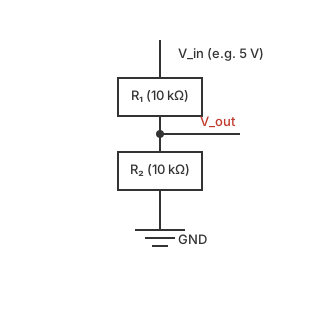
Put two resistors in series across a supply and the point between them sits at a fraction of the voltage, set by the ratio:
> V_out = V_in × (R₂ / (R₁ + R₂))
With 5 V in and two equal 10 kΩ resistors, the middle sits at 2.5 V. Make R₂ bigger than R₁ and the tap point rises; make it smaller and the tap falls. This is how you step a 5 V sensor signal down to the 3.3 V your microcontroller can read, how you set a comparator's trip point, and how you bias a transistor's base.
Calculating an LED current-limiting resistor
An LED is not a resistor; left directly across a supply it draws as much current as it can and burns out. You add a resistor to set the current. The formula:
> R = (V_supply − V_forward) / I
where V_forward (Vf) is the LED's rated drop (about 2 V for red, 3.2 V for blue/white) and I is the current you want (typically 20 mA = 0.020 A, but 10 mA is fine for indicator use).
Example: a red LED (Vf ≈ 2 V) on a 5 V rail, wanting 15 mA: R = (5 − 2) / 0.015 = 200 Ω. The nearest common E12 value is 220 Ω, which gives (5−2)/220 ≈ 13.6 mA — a safe, bright-enough choice. This is exactly why the [220 Ω resistor](/components/resistor/220-ohm-resistor) is the go-to LED part.
Common mistakes (and how to avoid a smoky resistor)
A short list of the errors that actually happen on the bench:
- Reading red as orange (or vice versa). They sit next to each other in the mnemonic and look similar under warm light. Red is 2 / ×100; orange is 3 / ×1 k. One band off is a 10× value error. Use the calculator, or measure with a meter, when it matters. - Under-rating the power. A resistor can be the right *value* and still overheat. Always run P = V² / R and leave headroom — a 1/4 W part should rarely sit above ~125 mW in real use. - Forgetting the derating curve. That 1/4 W number is for 70 °C and below. In a hot enclosure, it is not 1/4 W anymore. - Floating input pins. A pull-up or pull-down resistor only does its job if it is actually connected to the pin *and* to the rail. A missing or misplaced resistor is why a button "sometimes" works. - Mixing up tolerance needs. Do not pay for 1% parts in a LED limiter, and do not cheap out with 5% parts in a measurement divider. Match the tolerance to the job. - Assuming SMD size = value. A 1206 is not "more ohms" than a 0402; it just handles more watts. The number on the body is the value; the package is the power.
Where to go next
You now have the full picture: what a resistor is, how to read any value by eye or by number, why the standard values exist, how to keep a part from burning, and the three calculations that cover most real circuits. The next step is to put specific values to work.
- Browse the full [resistor category](/components/resistor) for every value we stock. - Need the classic LED limiter? Start at the [220 Ω resistor](/components/resistor/220-ohm-resistor). - Building a default current limiter or pull-up? The [1 kΩ resistor](/components/resistor/1k-ohm-resistor) is your friend. - Pulling up a microcontroller pin? That is the [10 kΩ resistor](/components/resistor/10k-ohm-resistor).
And when the math gets real, open it in CircuitForge's simulator — build the divider or the LED circuit, watch the node voltages and currents update live, and confirm the formula before you ever touch a soldering iron.
Questions I Get Asked
How do I read a resistor with no colors, just numbers?
That is a surface-mount part. Read the 3-digit, 4-digit, or EIA-96 code instead of a color band: a 3-digit code uses two significant figures plus a zero count (471 = 470 ohm), a 4-digit code adds a third significant figure (4700 = 470 ohm), and EIA-96 uses a two-digit E96 index plus a letter multiplier (01A = 100 ohm, 68A = 4.87 kohm). No stripes means it is a printed number system, not a color code.
What resistor do I need for an LED?
Use the formula R = (V_supply - V_forward) / I, where V_forward is the LED's rated drop (about 2 V for red, 3.2 V for blue/white) and I is the current you want (typically 15-20 mA). For a red LED on a 5 V rail wanting about 15 mA, that is roughly 200 ohm, so a standard 220 ohm resistor works perfectly and keeps the current safe.
Is a higher wattage resistor better?
Not automatically. A 1 W resistor placed where a 1/4 W part is specified works electrically (it simply runs cooler), but it is larger, more expensive, and may not fit the footprint. Size the wattage to the actual power dissipation plus headroom, and no more.
Why is my 1 kohm resistor measuring 980 ohm?
Because it is a plus-or-minus 5 percent part, and 980 to 1020 ohm is exactly within specification. If you need the value to stay tighter, buy a 1 percent metal-film resistor instead of a 5 percent carbon-film one.
Can I put resistors in parallel to share power?
Yes. Two equal resistors in parallel halve the current through each and double the combined power-handling capability. Just remember the combined resistance drops as well: two 10 kohm resistors in parallel equal 5 kohm.
What does the sixth band on a resistor mean?
On precision resistors, the sixth band is the temperature coefficient of resistance (TCR), given in ppm per degree Celsius. It tells you how much the resistance drifts as the part heats up. For most hobby circuits you can ignore it, but for measurement equipment it matters.
Do I need the 3D viewer or simulator to understand resistors?
No. The text and diagrams in this guide are enough to design with. The interactive 3D component viewer and live simulator just make it faster to see a physical part and prove a circuit works, which is why they are built into CircuitForge.
Written by Advik — building CircuitForge solo
I'm a student, not a professional electrical engineer — I don't have a degree or industry experience in electronics. I started CircuitForge because I wanted a better way to learn circuits myself, and I write these guides as I go.
Every article is backed by real research — datasheets, textbooks, and the references linked below — and I use AI tools as part of my research and writing process to help me work faster. I still check every technical claim myself before it goes up.
Found something wrong? I'd genuinely like to know — email me and I'll fix it fast.